
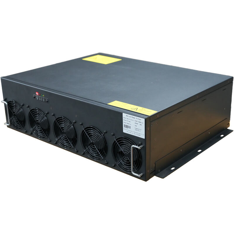
The main function of the PIAPF series active power filter is to filter out the harmonic current generated by the equipment. Its working mode is: real-time high-precision sampling - fast Fourier analysis - precise harmonic current output compensation.
By adopting an active and proactive approach, based on high-speed DSP device digital signal processing technology, fast Fourier transform and instantaneous reactive power theory algorithms, high-frequency PWM drive technology, etc., after rapid and successive detection and analysis of grid harmonics, within the same cycle, the PIAPF active power filter will emit harmonic currents in the opposite direction to those generated by the equipment. Harmonic currents of the same frequency and amplitude are actively filtered out.
This product complies with the JB/T 11067-2011 "Low-Voltage Power Active Power Filter Device" standard and has obtained the third-party type test report.
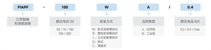
The rated filter current of a single module is 50A / 75A / 100A / 150A / 200A
The maximum filtering current for a single cabinet is 800A
◆ Fast: Dynamic real-time tracking and compensation, fast response speed, instantaneous response time ≤ 1ms, full response time ≤ 10ms
◆ Fine: Advanced FFT and symmetrical component algorithm, capable of full compensation or selective compensation for 2nd to 61st harmonic components, with fine filtering
◆ High efficiency: Under the condition of sufficient power configuration, the harmonic content is maintained at ≤ 5%, with high filtering efficiency, low power loss, and is not affected by grid impedance
◆ Stability: The perfect LCR output circuit and software damping algorithm automatically suppress overload, with no resonance risk. Multiple protection functions ensure the safe and reliable operation of the system
◆ Integration: It can compensate for harmonic current, reactive power and balance three-phase load, with multiple functions in one machine
◆ Intelligence: Self-diagnosis of faults, historical event recording, RS485 interface + standard MODBUS communication protocol, remote monitoring
Component composition
◆ IGBT high-frequency power power electronic switch
◆ High-quality DC support energy storage system
◆ LCR output module
◆ DSP data processing and communication components
◆ FPGA Pulse and protection logic processing components
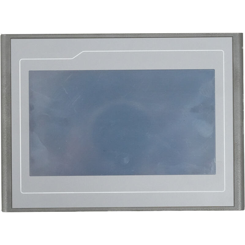
◆ Touch LCD display screen, efficient UI interface
|
Working Power Supply |
|
|
Rated Voltage |
AC400V±15% (AC690V±15%), three-phase four-wire |
|
Rated Power Consumption |
≤3% of rated compensation capacity |
|
Rated Frequency |
50±5Hz 50±5 Hertz |
|
Overall Efficiency |
>98% |
|
Performance Indicators |
|
|
Filtering Capacity |
THDi (Total Harmonic Distortion of Current) ≤ 3% |
|
Filtering Range |
2nd ~ 61st harmonics, elimination of specified harmonics |
|
Harmonic Filtration Rate |
>97% (compensation current limit can be set for each harmonic) |
|
Neutral Line Filtering Capacity |
3 times of phase line |
|
Instantaneous Response Time |
<1ms <1 millisecond |
|
Full Response Time |
<10ms <10 milliseconds |
|
Switching Frequency |
20KHz |
|
Operating Noise |
<60dB <60 decibels |
|
Mean Time Between Failures |
≥10000 hours |
|
Operating Environment |
|
|
Ambient Temperature |
-10℃~+45℃ -10°C~+45°C |
|
Storage Temperature |
-40℃~70℃ -40°C~70°C |
|
Relative Humidity |
≤95% at 25℃, no condensation |
|
Altitude |
≤2000m, customizable for exceeding standards |
|
Atmospheric Pressure |
79.5~106.0Kpa 79.5~106.0Kpa |
|
Surrounding Space |
No flammable and explosive media, no conductive dust and corrosive gases |
|
Insulation and Protection |
|
|
Primary and Enclosure |
AC2500V for 1min, no breakdown or flashover |
|
Primary and Secondary |
AC2500V for 1min, no breakdown or flashover |
|
Secondary and Enclosure |
AC2500V for 1min, no breakdown or flashover |
|
Safety Protection Level |
IP30 |
• Design and Selection
Harmonic Capacity Design
For large-capacity harmonic sources, on-site treatment is suitable, and point-to-point treatment is more economical and reasonable; for small-capacity distributed harmonic sources, due to large harmonic fluctuations and many random factors, resulting in irregular changes in harmonic orders and contents, centralized treatment is suitable.
Due to the flow and fluctuation characteristics of harmonics, if it is necessary to design a harmonic treatment scheme or a harmonic filtering device, harmonic data can be tested by a power quality analyzer. This situation is applicable to the harmonic treatment of power grids with already commissioned equipment or power grids that need capacity increase. Of course, to ensure the reliability and accuracy of test data, it is necessary to be familiar with the working principle and process of harmonic sources, understand the power grid structure, and adopt reliable harmonic testers and accurate test methods in accordance with the requirements of Appendix D in GB/T 14549-1993 "Power Quality - Public Power Grid Harmonics". However, for new projects that are only in the design stage, electrical designers cannot obtain sufficient harmonic data of electrical equipment. In view of this, through tests and experience summaries in many industries, empirical formulas are obtained for electrical designers to refer to when designing and drawing.
The following empirical formulas can meet the design requirements, and the active filtering device can be selected according to the calculated harmonic current.
◆ Centralized Treatment:
Centralized compensation is applicable to power distribution systems with many types of loads, a large number of scattered nonlinear loads, and small harmonic content of a single nonlinear load. PIAPF active filtering devices can be installed at the low-voltage incoming line end of the power grid to comprehensively treat harmonics existing in the power distribution system.
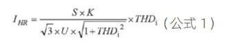
* Note: The above formula is applicable to centralized treatment on the secondary side of the transformer.
Where: S: capacity of the transformer; U: rated voltage of the secondary side of the transformer; K: load rate; IHR: harmonic current; THDi: total harmonic distortion rate of current.
Value Range:
K represents the load rate of the transformer, and its value range in transformer design is 0.6~0.85; THDi is the only variable in the above formula, and its value range depends on different industries and different loads in each industry.
◆ On-site Treatment:
On-site compensation is applicable to power distribution systems with a single large harmonic content and distributed distribution. Installing PIAPF active filters at the input end of the load can achieve ideal treatment effects. If there is a high-power harmonic source load in the power distribution, on-site treatment can also be carried out at the input end of the load. It can be calculated using Formula 2 below.
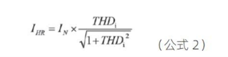
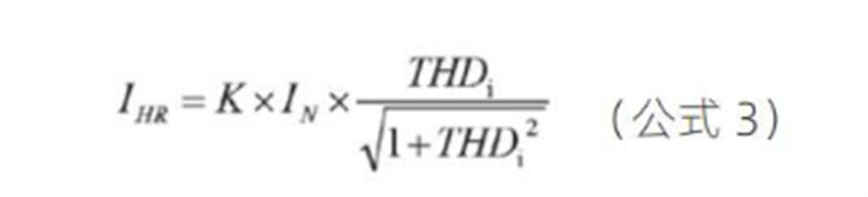
Where I represents the rated current of the equipment. The above formula only considers the operation of the load under full load (K=1). The actual operating NK value should be considered in the design, as shown in Formula 3.
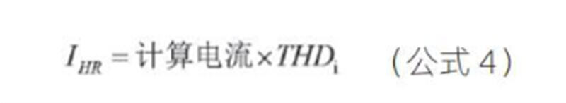
◆ Estimation Formula:
The estimation Formula 4 can be used in daily design:
Based on the harmonic current calculated above, and according to the existing models of PIAPF products, determine the capacity to be installed. The installed capacity of PIAPF can be selected according to Formula 5, and the preceding coefficient is to ensure that the APF has a certain margin.
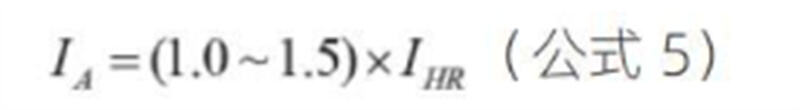
IA represents the installed capacity of APF, and IHR represents the harmonic current.
Note: From the above analysis, it can be concluded that THDi is the main variable to be determined, and its value can refer to "APF Selection Quick Reference Table" and "Summary of Harmonic Treatment in Various Industries".
Summary of Harmonic Treatment in Various Industries
|
Industry Type |
Harmonic Source Loads |
Recommended THDi |
Treatment Method |
|
Office Buildings |
Computer equipment, central air conditioners, various energy-saving lamps, office electrical equipment, large elevators |
15% |
Centralized treatment |
|
Medical Industry |
Important medical equipment: nuclear magnetic resonance equipment, accelerators, CT, X-ray machines, UPS, etc. |
20% |
Centralized treatment |
|
Communication Rooms |
High-power UPS, switching power supplies |
20%~25% |
On-site treatment or centralized treatment |
|
Public Facilities |
Thyristor dimming systems, UPS, central air conditioners |
25% |
Centralized treatment |
|
Banking and Finance |
UPS, electronic equipment, air conditioners, elevators |
20% |
Centralized treatment |
|
Manufacturing |
Frequency conversion drives, DC speed regulation drives |
20% |
Centralized treatment |
|
Water Treatment Plants |
Frequency converters, soft starters |
40% |
On-site treatment or partial treatment |
|
Other Industries |
Hot rolling mills, cold rolling mills, spot welders, intermediate frequency furnaces, arc furnaces, DC motors, frequency converters, electrolytic cells, etc. |
≥50% |
On-site treatment or partial treatment |
Main Characteristic Harmonics Generated by Various Load Equipment
|
Nonlinear Load Equipment |
Main Harmonic Components |
||||
|
3rd |
5th |
7th |
11th, 13th and higher harmonics |
||
|
Elevators, escalators, lifts and hoisting machinery |
● |
●●● |
●● |
● |
|
|
Frequency converters, soft starters, computers, data equipment, communication equipment, etc. |
● |
●●● |
●● |
● |
|
|
UPS |
Single-phase |
●●● |
●● |
● |
● |
|
Three-phase |
- |
●●● |
● |
● |
|
|
Fluorescent lamps, metal halide lamps, dimming lamps and other nonlinear lighting equipment |
●●● |
●● |
● |
● |
|
|
Rectifiers, DC equipment and chargers |
● |
●●● |
●● |
● |
|
|
Emergency generator sets, electric welders and arc welding equipment |
●●● |
●● |
● |
● |
|
The number of ● indicates the pollution degree of the harmonic source. ●●● indicates severe pollution; ●● indicates moderate pollution; ● indicates slight pollution.
Generally, equipment containing single-phase rectifier circuits has all odd harmonics in its characteristic harmonic spectrum.
The characteristic harmonics of three-phase rectifier equipment conform to the following rules: equipment containing six-pulse rectifier circuits has characteristic harmonic frequencies of 5, 7, 11, 13, 17, 19..., i.e., 6K±1, where K=1, 2, 3... are natural integers; when the internal rectifier circuit of the equipment is 12-pulse, its characteristic harmonic frequencies are 11, 13, 23, 25..., i.e., 12K±1, where K=1, 2, 3... are natural integers.
Copyright © Nantong Zhifeng Electric Power Technology Co., Ltd. All Rights Reserved - Privacy Policy - Blog